Our laser cutting service is ideal for making custom parts out of various sheet materials. Capabilities include cutting, scoring, and engraving with our laser cutters, plus color UV-printing. Pricing starts at $25, and most orders ship in three business days. We also offer expedited services, up to our same-day service; local customers can pick up parts the same day, or have them shipped to your door the very next day!
Laser cutting is ideal for quickly making custom parts out of sheets of plastic, wood, card stock, rubber, or metal. All you have to do is draw your design on a computer, and you can have a completely custom part delivered as quickly as the next day! Once you have your design ready, it is easy to order a single copy, or large volumes.
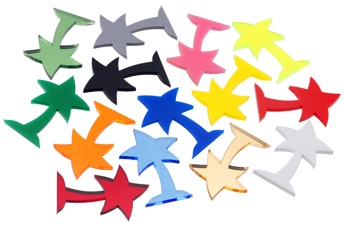
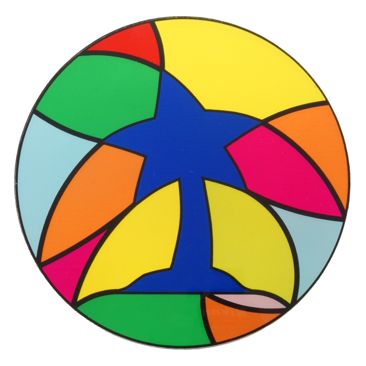
Laser-cut Pololu logos in a variety of colors of acrylic.
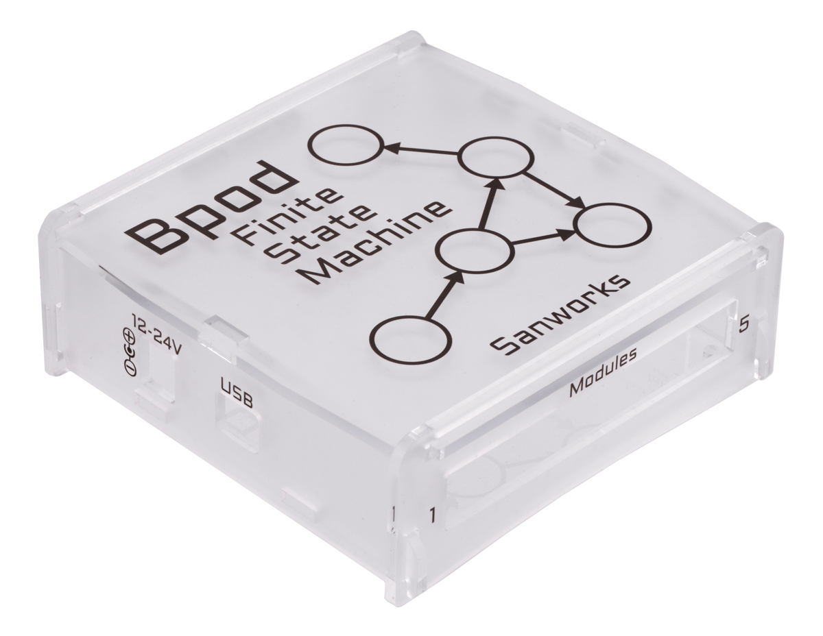
Laser-cut and UV-printed acrylic enclosure.
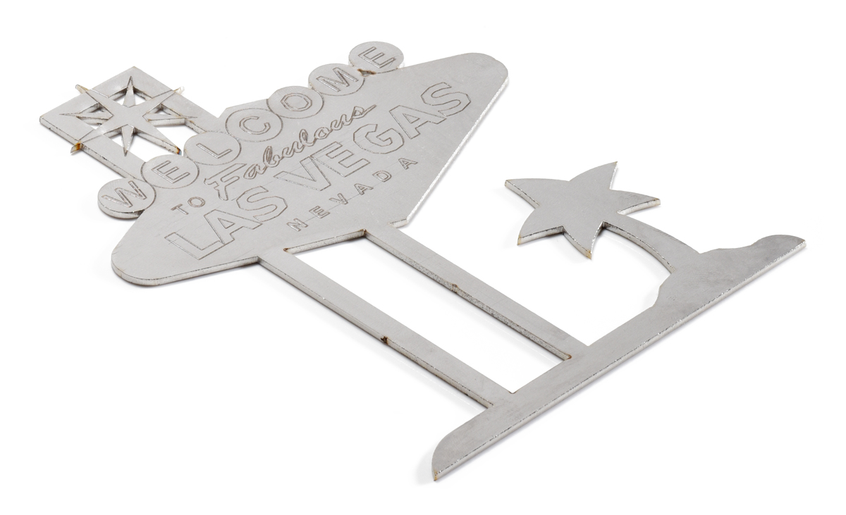
Laser-cut stainless steel.
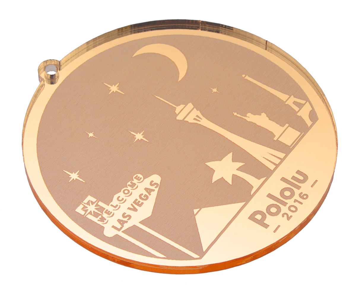
Pololu ornament, laser-cut and reverse-engraved on mirrored acrylic.
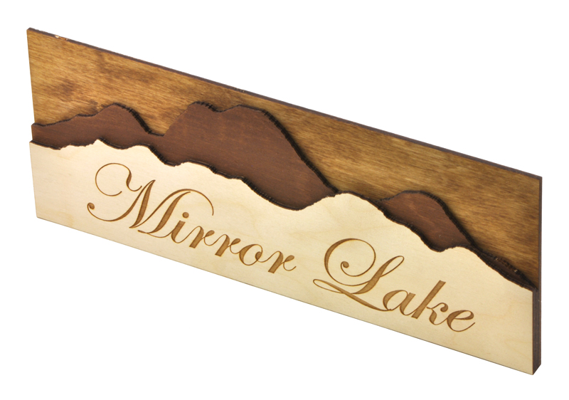
Laser-cut and raster-engraved wedding table sign (11"×4") cut from 1/8" birch plywood.
Laser-cut and UV-printed acrylic.
With our custom part cutting service, you can quickly and economically create intricate designs that are too complex for creating by hand. You can cut smooth curves and laser engrave text or logos onto your parts. You can even add vibrant and colorful labels, logos, photos, and artwork using our UV-printing service. The only restriction is that parts are flat, but you can make three-dimensional robots by combining multiple two-dimensional pieces. Of course, non-robot parts are welcome – our laser cutting service is great for anyone with a project requiring custom parts!
Even if you do not have access to a computer with the software necessary to draw your part, we might be able to draw your part for you.
We email you your quote and PDF proofs for approval.
You select a turn time and place your order, and we cut and ship your parts.
Laser cutting materials and capabilities
We can laser cut, score, and engrave various thicknesses of plastics, woods, metals, paper, cloth, and more up to 47.5″ × 47.5″ (121 cm × 121 cm). We stock acrylic, ABS, acetal/POM (Delrin®), styrene, birch plywood, aluminum, steel, and more, and we can quickly obtain many other materials through our suppliers. You can also ship us your materials.
We cannot laser cut metals thicker that 1/4″ (6.35 mm), copper, PVC, polycarbonate (Lexan), carbon fiber, or any materials containing chlorine (please consider OSH Cut for metals that we cannot cut).
We can add vibrant and colorful artwork with up to 1200 DPI resolution by printing layers of UV-cured full-color CMYK, white, primer, and clear inks directly onto a part or part layout up to 24″ × 16.5″ (61 cm × 42 cm). We can print onto many of the materials we can laser cut, but our inks are best suited for rigid materials.